







What Determines Lithium Battery Cycle Life in Real Applications?
Lithium battery cycle life is often presented as a single number: 2,000 cycles, 4,000 cycles, 6,000 cycles, or more. In real applications, however, the number printed on a datasheet is only part of the story. A battery that performs well under controlled laboratory conditions may age very differently when installed in an energy storage system, electric vehicle, industrial machine, or other demanding application.
So, what affects lithium battery cycle life once a battery leaves the test bench?
The answer is not one factor but a chain of interacting conditions. State of charge (SOC), depth of discharge (DOD), charge and discharge rate, operating temperature, cell consistency, and battery management system (BMS) strategy all influence how quickly a lithium battery loses usable capacity and increases in internal resistance.
Understanding these factors helps system designers make better decisions about cell selection, pack configuration, thermal management, charging strategy, and BMS settings. It also explains why two battery packs built with similar cells can deliver very different service lives in the field.

[*With the repeated charging and discharging, the capacity of the cell will gradually decline.Usually when the cell's capacity reaches 70% of the nominal capacity, the number of charge-discharge cycles is called cycle life.]
Table of Contents
SOC: Why State of Charge Matters
DOD: How Depth of Discharge Influences Cycle Life
C-Rate: The Impact of Charge and Discharge Current
Temperature: A Major Driver of Battery Aging
Cell Consistency: Why the Weakest Cell Matters
BMS: Turning Cell Capability Into Pack-Level Cycle Life
How These Battery Cycle Life Factors Work Together
How to Extend LiFePO4 Battery Lifespan in Real Applications
Final Thoughts
1. SOC: Why State of Charge Matters
State of charge, or SOC, describes the amount of usable energy remaining in a battery relative to its available capacity. A battery at 100% SOC is fully charged according to its defined operating limits, while a battery near 0% SOC is close to its lower discharge limit.
SOC is important because lithium-ion cells do not age at the same rate across their entire voltage range. Keeping a battery continuously at a very high SOC can accelerate calendar aging, particularly when high SOC is combined with elevated temperature.
High SOC Can Increase Electrochemical Stress
At high SOC, cell voltage is also relatively high. Depending on the lithium-ion chemistry, prolonged exposure to these conditions can promote unwanted side reactions inside the cell.
This does not mean a battery should never reach 100% SOC. Many applications require maximum available energy. The important question is how long the battery remains at high SOC and under what temperature conditions.
For example, a backup battery that is charged to its upper limit and then remains fully charged in a hot enclosure may experience a different aging profile from a battery cycling regularly through a moderate SOC range.
SOC Window Is an Engineering Decision
System designers can define an operating SOC window instead of using the full theoretical capacity of a cell.
For example, a system might operate between 10% and 90% SOC or between 20% and 80% SOC. This reduces the usable energy available during each cycle, but it may reduce electrochemical stress and improve long-term durability.
The optimum SOC window depends on:
Required usable energy
Battery chemistry
Expected operating temperature
Required service life
Charge and discharge power
Application duty cycle
Safety margins
Total cost of ownership
This is one reason battery cycle life cannot be evaluated by looking at nominal capacity alone.
2. DOD: How Depth of Discharge Influences Cycle Life
Depth of discharge indicates how much of a battery's capacity is removed during a discharge cycle.
If a fully charged battery delivers 80% of its available capacity before being recharged, it has experienced approximately 80% DOD. A shallower cycle might use only 20% or 30% of available capacity.
Among the major battery cycle life factors, DOD is especially important because it determines how deeply the cell is cycled during regular operation.
Why Deeper Cycles Usually Create More Wear per Cycle
A deep discharge requires the electrodes to operate across a wider electrochemical range. Repeated deep cycling generally creates more degradation per individual cycle than shallow cycling under otherwise comparable conditions.
This relationship is why DOD battery life should not be evaluated only by counting cycles.
A battery completing thousands of shallow cycles and a battery completing fewer deep cycles may deliver comparable-or very different-total energy throughput over their service lives. The answer depends on chemistry, operating conditions, and the manufacturer's cycle-life test methodology.

Cycle Count vs. Energy Throughput
Consider two simplified operating strategies:
| Operating Strategy | Typical DOD | Relative Stress per Cycle | Usable Energy per Cycle |
|---|---|---|---|
| Shallow cycling | 20–40% | Lower | Lower |
| Moderate cycling | 50–80% | Moderate | Moderate to high |
| Deep cycling | 80–100% | Higher | Highest |
The key engineering metric is therefore not always the maximum possible cycle count.
For stationary energy storage, commercial equipment, and other high-utilization applications, total lifetime energy throughput can be more useful than cycle count alone. A battery must deliver enough usable energy over its lifetime to justify its cost and meet application requirements.
Choosing the Right DOD
There is no universal "best" DOD.
A solar storage system may prioritize long service life and operate within a controlled DOD window. An emergency application may prioritize maximum available energy because deep discharge occurs infrequently. A mobility application may need a different balance between range, battery weight, and durability.
When evaluating DOD battery life, compare cycle-life data at the same DOD, temperature, C-rate, and end-of-life criterion. Otherwise, two cycle-life specifications may not be directly comparable.
3. C-Rate: The Impact of Charge and Discharge Current
C-rate expresses current relative to battery capacity.
For a 100Ah battery, a 1C discharge corresponds to approximately 100A, while a 0.5C discharge corresponds to approximately 50A. The same principle applies to charging.
Higher C-rates can be useful when an application requires rapid charging or high power, but they also influence heat generation, voltage behavior, and cell aging.
Higher Current Means More Internal Heating
Every battery has internal resistance. When current passes through the cell, some energy is converted into heat.
As current increases, heat generation can rise substantially. This means aggressive charge or discharge rates can expose cells to higher internal temperatures even when ambient temperature appears acceptable.
High current can also increase voltage differences between cells in a pack, particularly when cell resistance or capacity is not well matched.
Fast Charging Requires More Than a High-Power Charger
Fast charging is not simply a matter of supplying more current.
The cell must be designed for the required charging rate, and the battery system needs appropriate thermal management, voltage monitoring, current control, and protection logic. Charging conditions may also need to change according to temperature and SOC.
For applications where long service life is more important than minimum charging time, a moderate charge rate can often reduce unnecessary stress.
Match C-Rate to the Real Duty Cycle
Engineers should evaluate more than a single maximum-current number. A realistic duty-cycle analysis should consider:
Continuous discharge current
Peak discharge current
Peak duration
Average current
Regenerative or pulse charging
Normal charging rate
Fast-charging frequency
Rest periods between high-power events
Cooling capability
A battery that experiences occasional short power peaks may age very differently from one operating continuously near its maximum current.
This distinction is essential when determining what affects lithium battery cycle life in high-power equipment.
4. Temperature: A Major Driver of Battery Aging
Temperature affects almost every process inside a lithium-ion battery.
High temperatures can accelerate unwanted chemical reactions and long-term degradation. Low temperatures increase internal resistance and can reduce available power and capacity. Charging at excessively low temperatures can create additional risks for some lithium-ion chemistries.
That makes thermal management one of the most important design considerations for battery longevity.
High Temperature Accelerates Aging
Heat can accelerate chemical degradation within a cell. When high temperature is combined with high SOC or high current, the effects can become even more significant.
This interaction matters in real installations.
A battery pack installed inside a poorly ventilated cabinet may operate well above ambient temperature. Similarly, cells located in the center of a densely packed module can experience different thermal conditions from cells near the enclosure wall.
The relevant parameter is therefore not simply room temperature-it is cell temperature during actual operation.
Low Temperature Creates Different Challenges
Cold conditions slow electrochemical processes and increase cell impedance. As a result, the battery may temporarily provide less usable capacity or power.
Charging requires particular attention. Depending on cell chemistry and manufacturer specifications, aggressive charging at low temperature may accelerate degradation or create unsafe conditions.
A well-designed BMS should therefore adjust or restrict charging according to measured cell temperature.
Temperature Uniformity Matters Too
Average temperature alone does not tell the whole story.
If one section of a pack operates consistently hotter than another, cells can age at different rates. Over time, this creates capacity and resistance differences that make pack balancing increasingly difficult.
Good thermal design aims to control both:
1. Absolute temperature: keeping cells within their specified operating range.
2. Temperature difference: minimizing thermal gradients between cells and modules.
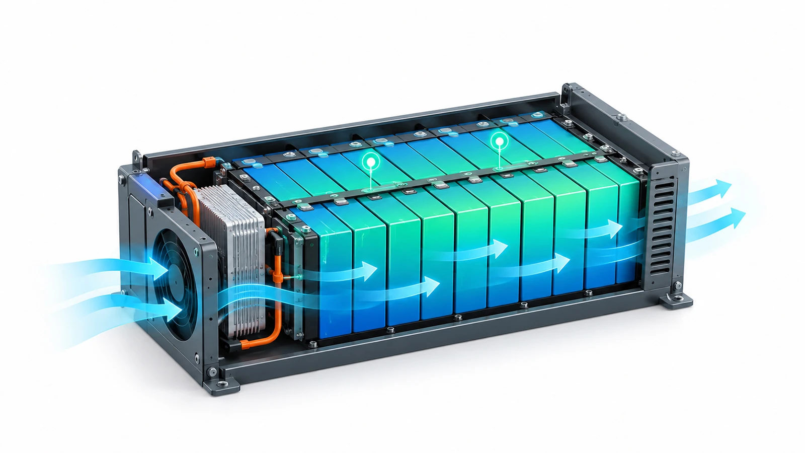
For demanding battery systems, thermal design should be considered during the mechanical and electrical design stages-not added after the pack architecture has already been finalized.
5. Cell Consistency: Why the Weakest Cell Matters
A battery pack is only as effective as the cells working together inside it.
In a series-connected pack, cells carry the same current, but their capacity, internal resistance, SOC, temperature, and aging rate may not remain identical. Small differences at the beginning of life can grow over hundreds or thousands of cycles.
This is why cell consistency is one of the most underestimated battery cycle life factors in real-world battery systems.
Capacity and Resistance Differences Accumulate
Suppose most cells in a pack have similar capacity, but one cell has slightly lower usable capacity.
During charging, that cell may reach its upper voltage limit earlier than the others. During discharge, it may reach the lower voltage limit first.
The BMS must protect that weakest cell, which means the entire pack may need to stop charging or discharging even though the remaining cells still have available capacity.
Over time, this can reduce pack-level usable energy.
Cell Matching Starts Before Pack Assembly
Good pack performance begins with appropriate cell selection and manufacturing control.
Important matching parameters can include:
Cell capacity
Open-circuit voltage
Internal resistance
Self-discharge behavior
Cell age and production batch
Electrochemical characteristics
Temperature behavior
Matching alone cannot prevent aging, but reducing initial variation gives the BMS a better starting point for maintaining balance.
Mechanical and Thermal Consistency Also Matter
Electrical matching is only part of the equation.
Cells should experience reasonably consistent mechanical, electrical, and thermal conditions throughout the pack. Uneven busbar resistance, cooling airflow, contact resistance, or mechanical pressure can cause nominally matched cells to age differently.
For OEMs and system integrators, this is why selecting the right battery cells should be considered together with pack engineering rather than as a separate purchasing decision.
6. BMS: Turning Cell Capability Into Pack-Level Cycle Life
The battery management system is the control layer connecting cell capability with real-world operation.
A high-quality cell can still experience shortened service life if the BMS permits inappropriate voltage, current, temperature, or SOC conditions. Conversely, a properly configured BMS can help keep cells within the operating window for which they were designed.
What the BMS Controls
Depending on system architecture, a BMS may monitor and manage:
Individual cell voltage
Pack voltage
Charge and discharge current
Cell and module temperature
SOC
State of health (SOH)
Cell balancing
Overcharge protection
Over-discharge protection
Overcurrent protection
Short-circuit protection
Charging and discharging limits
Communication with chargers, inverters, or vehicle controllers
These functions directly influence how cells experience everyday use.
Cell Balancing Protects Usable Pack Capacity
As cells gradually drift apart in SOC, balancing becomes increasingly important.
Passive balancing typically removes small amounts of energy from higher-voltage cells to help the pack converge toward a more uniform state. Active balancing systems can transfer energy between cells or groups of cells, depending on the architecture.
The goal is not merely to make voltage readings look similar. Effective balancing helps prevent individual cells from prematurely reaching upper or lower protection thresholds.
BMS Limits Should Match the Cell
A common design mistake is treating BMS protection thresholds as universal values.
They are not.
Voltage limits, current limits, temperature limits, balancing thresholds, and charging strategies should be selected according to the actual cell specification and application requirements.
The BMS should also coordinate with the rest of the system. In an energy storage application, for example, communication between the battery and inverter can allow power limits to be adjusted dynamically rather than relying only on emergency protection cutoffs.
For custom battery projects, battery solution design should therefore consider the cells, BMS, thermal system, mechanical structure, charger or inverter, and application duty cycle as one integrated system.
7. How These Battery Cycle Life Factors Work Together
One of the biggest mistakes in battery life analysis is evaluating each factor independently.
In practice, SOC, DOD, C-rate, temperature, cell consistency, and BMS strategy interact continuously.
A high discharge rate creates additional heat. Higher cell temperature may accelerate aging. Uneven cooling can cause some cells to age faster. Those cells then develop different capacity or resistance characteristics, requiring more balancing and potentially causing the BMS to reach protection thresholds sooner.
The relationship can be summarized as:
SOC window → DOD → current demand → heat generation → cell divergence → BMS response → pack-level cycle life

Example: Stationary LiFePO4 Energy Storage
Consider a LiFePO4 energy storage battery used for daily solar cycling.
The cells may have excellent laboratory cycle-life performance, but field life will depend on questions such as:
Does the battery remain at 100% SOC for long periods?
How deeply is it discharged every day?
What is the normal charging rate?
How hot does the cabinet become during summer?
Are cells thermally and electrically well matched?
Does the BMS balance cells effectively?
Does the inverter respect dynamic battery limits?
Changing just one of these variables can alter the operating conditions experienced by the entire battery.
This is why datasheet cycle life should be treated as a test result under defined conditions, not an unconditional prediction of service life.
8. How to Extend LiFePO4 Battery Lifespan in Real Applications
LiFePO4 is widely selected for applications where safety, durability, and long-term cycling are important. However, chemistry alone does not guarantee long service life.
To extend LiFePO4 lifespan, the complete battery system must keep cells within appropriate electrical and thermal operating conditions.
1. Use an Appropriate SOC Window
Avoid keeping the battery unnecessarily at extreme SOC levels when the application does not require it.
A narrower operating window can trade a portion of nominal capacity for lower cell stress. The optimum limits should be based on application requirements and the cell manufacturer's specifications.
2. Optimize DOD for the Application
Do not automatically design every cycle around maximum usable capacity.
If the system has sufficient installed capacity, reducing routine DOD may improve longevity. Evaluate the tradeoff between battery size, usable energy, lifetime throughput, and replacement cost.
3. Avoid Unnecessary High C-Rates
Specify charge and discharge currents according to actual power requirements.
Oversizing current capability where needed can reduce the time cells spend operating close to their limits. For high-power systems, ensure that electrical connections and thermal management are designed for the expected current.
4. Control Cell Temperature
Keep cells within their specified temperature range and minimize temperature differences throughout the pack.
Thermal monitoring should cover representative locations rather than relying on a single sensor that may not detect local hot spots.
5. Start With Consistent Cells
Cell quality and consistency matter from day one.
Appropriate incoming inspection, sorting, matching, assembly processes, and traceability can reduce pack variation and support more predictable aging.
6. Configure the BMS for the Actual Cell and Application
Do not rely on generic BMS settings.
Voltage thresholds, temperature limits, current limits, balancing logic, and SOC algorithms should reflect the selected cells and real operating environment.
7. Validate Under Realistic Conditions
Laboratory testing should reproduce the expected application as closely as practical.
That means testing representative DOD, SOC windows, C-rates, ambient temperatures, cooling conditions, and charging profiles-not simply running a generic cycle test.
A practical strategy to extend LiFePO4 lifespan is therefore not a single setting or component. It is a coordinated system design that manages stress throughout the battery's service life.
9. Datasheet Cycle Life vs. Real-World Battery Life
When comparing lithium batteries, it is tempting to choose the product with the largest cycle-life number. But the number is meaningful only when its test conditions are understood.
Before comparing two batteries, check:
DOD used during testing
Charge and discharge C-rate
Test temperature
Upper and lower voltage limits
Rest periods
End-of-life capacity criterion
Cell-level vs. pack-level testing
For example, "6,000 cycles" without test conditions provides much less engineering information than a cycle-life specification that clearly defines DOD, temperature, current, and remaining capacity at end of test.
This is particularly important when investigating what affects lithium battery cycle life, because changing the test conditions can significantly change the resulting cycle count.
Ask for the Data Behind the Number
OEM buyers and system integrators should look beyond headline specifications.
Request detailed cell and battery data relevant to your intended application. Where possible, compare performance curves rather than isolated marketing numbers.
For a custom project, provide the battery supplier with a realistic duty cycle, including expected current, DOD, SOC range, temperature, daily operating hours, and required service life. Better input data enables more appropriate cell and pack selection.
10. Final Thoughts
Lithium battery cycle life is not determined by chemistry alone, and it cannot be predicted accurately from one number on a datasheet.
The most important factors form an interconnected chain: SOC affects the electrochemical operating range; DOD determines cycling depth; C-rate determines current stress and heat generation; temperature influences reaction rates and resistance; cell consistency determines pack balance; and the BMS controls how the complete system responds to all of these conditions.
Understanding what affects lithium battery cycle life allows engineers to move beyond simple cycle-count comparisons and evaluate what really matters: reliable energy delivery over the intended service life.
For LiFePO4 systems in particular, long life begins with appropriate cells but depends equally on pack design, thermal management, operating strategy, and BMS configuration.
At greatech energy, battery selection and system design can be evaluated around the requirements of the real application-from battery cells and pack configuration to BMS communication and energy storage integration.


